Hello, this is K10-K10.
The main PCB for the 2027 season (Kanto region spec) is finally complete!
Once again, I manufacturing this board through JLCPCB.
Schematic & Layout
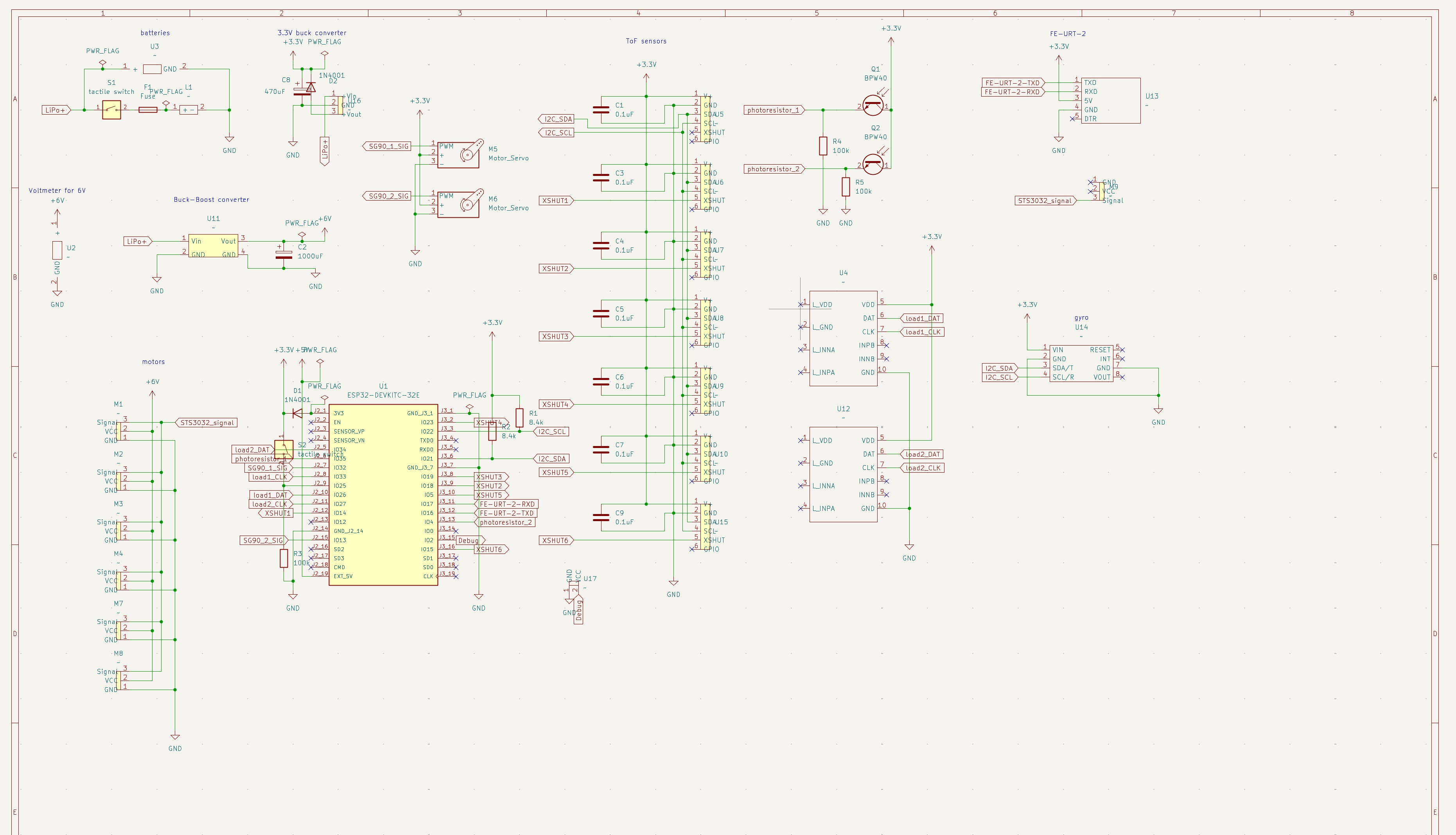
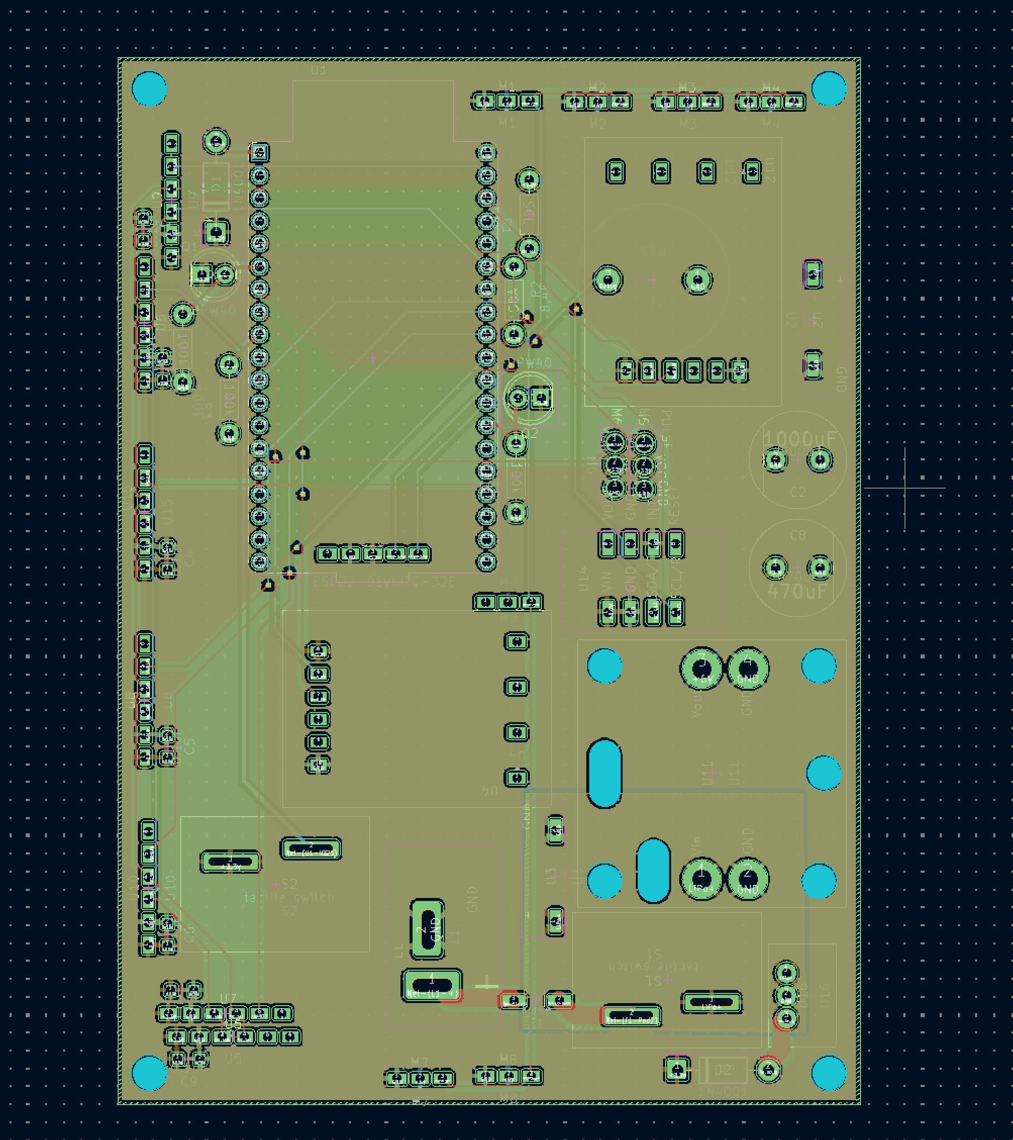
The entire system is consolidated into a single main board.
For this iteration, I adopted a 4-layer structure, dedicating specific internal layers as full GND, 3.3V, and 6V planes.
In the previous year’s model, only the motors were powered directly by the LiPo battery, while the rest of the circuits drew power from the ESP32 pins. In this new design, I integrated dedicated 3.3V and 6V DC-DC converters to supply stable power to both the sensors and motors directly from the LiPo battery, significantly improving power stability.
Due to the increased number of components compared to last year, the ESP32 GPIO pin assignment was cut extremely close.
PCB Photos
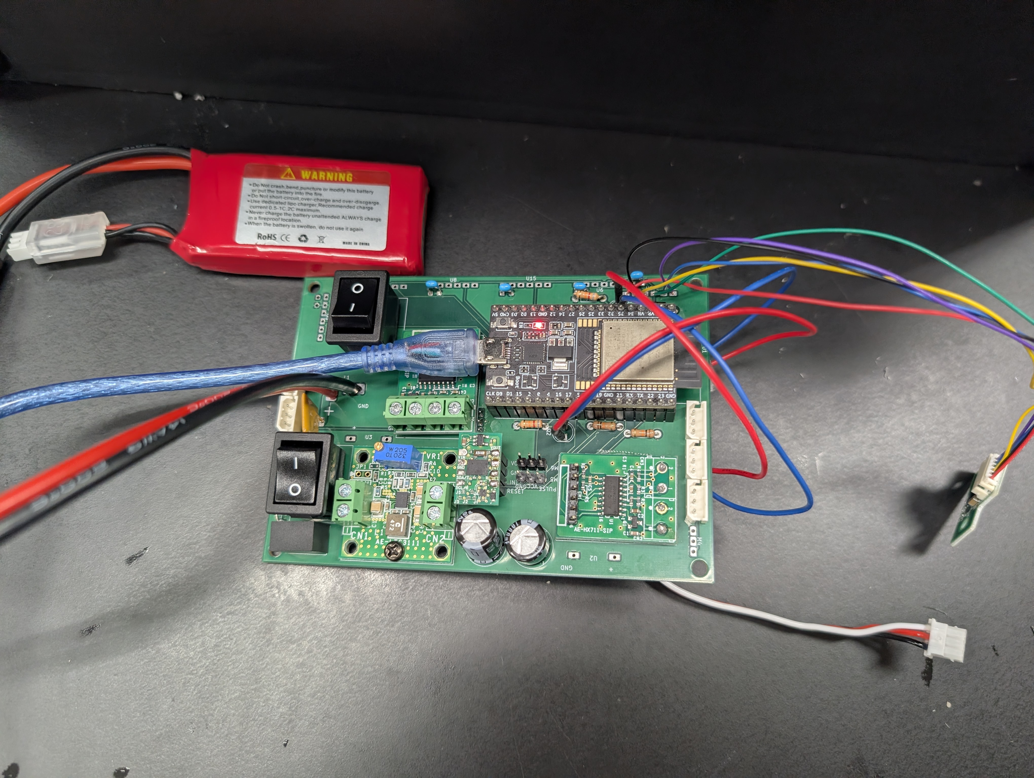
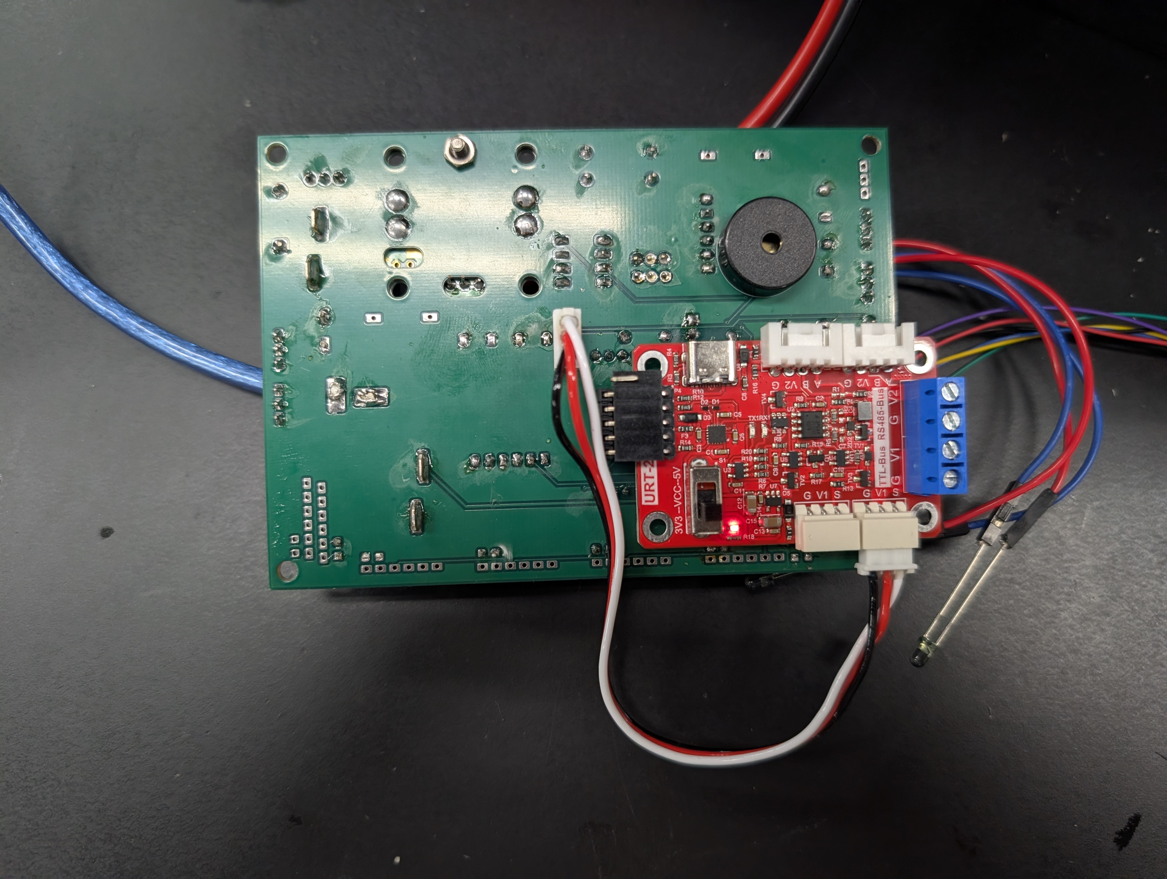
Since our robot design relies on a camera for line tracing, I needed to reserve a large open space in the center of the robot chassis. This required minimizing the PCB footprint as much as possible. To achieve this compact form factor, the buzzer and the motor URT interface board are strategically mounted on the back side of the PCB.
Key Improvements from Last Year
Previously, I used ultrasonic sensors (one on the front-left and one on the front-right) for distance measurement. This year, I have upgraded to ToF (Time-of-Flight) sensors.
By placing two ToF sensors on each front corner (four in total for the front-sides), the robot can now handle the “Rescue Zone evacuation,” which was a major hurdle last year.
Additionally, I’ve designed a bumper utilizing load cells, which should make obstacle avoidance much smoother.
I also added an onboard buzzer for debugging, which is going to drastically boost development efficiency.
Parts List
The primary computing unit is a Raspberry Pi 5, while an ESP32-DevKitC-32E is onboard to handle low-level control for the motors and sensor array.
For the drivetrain, I am using four Feetech STS3032 serial servos, as mentioned in previous post. Huge thanks to Feetech for their support!
The rescue arm mechanism is planned to use either an SG90 or an STS3032.
Here are the main sensors and components populated on or connected to the board:
| Component / Sensor | Qty | Description / Use Case |
|---|---|---|
| LTC3111 | 1 | Buck-boost DC-DC converter for the 6V rail. |
| M78AR033-0.5 | 1 | 3.3V switching regulator (DC-DC converter). |
| BNO055 | 1 | 9-axis IMU. Used for slope detection and attitude control. |
| ToF VL53L0X | 6 | Measures distance to walls (2 units each for front-left/right sides). |
| Load Cell SC616C (1kg) | 2 | Used for contact detection on the front bumper. |
| HX711 AD Converter | 2 | Amplifier module to read load cell values via ESP32. |
| NJL7502L | 2 | Phototransistor to detect successful victim rescue. |
| FE-URT-1 | 1 | Interface board to control the STS3032 servos. |
| PKM22EPPH4001-B0 | 1 | Onboard buzzer for debugging and status alerts. |
Note: Resistors, decoupling capacitors, and connectors are placed appropriately throughout the circuit.
Known Issues & Workarounds
While testing the board, I discovered a couple of gremlins:
-
Power Leakage via Switch Even when unplugging the programming cable from the ESP32, power leaks through the switch circuit, keeping it turned on. However, since I don’t unplug the cable often during operation, and turning off the program requires hitting the switch anyway, this shouldn’t be a major issue in practice.
-
Faulty Photoreflector Circuit Due to a potential design oversight in the schematic, the photoreflectors (NJL7502L) intended for victim detection are not functioning correctly. To bypass this, I plan to offload the victim detection logic to the camera on the Raspberry Pi 5. Handling this via software should completely cover the required functionality.
-
Physical Interference Between Switch and Cable The ESP32 communication cable physically interferes with the power switch when plugged in. Frustratingly, I made the exact same layout mistake in the previous iteration. Improving the orientation and placement of connectors and switches is definitely a top priority for my next hardware spin.
Fortunately, all other core sensors are working perfectly, which is a huge relief.
Conclusion
The design files for this PCB (schematics, layouts, etc.) are open-source and available on GitHub. Feel free to check it out!
techno-robocup/robocup2027-pcb-data
With far more sensors and features than last year, this is shaping up to be a highly capable robot. Once the physical chassis is fully assembled, I’ll dive straight into software development.
~Thank you for reading~